Separate the household from my room
The main division is between the network everyone else uses and the connection serving my room. That boundary is the basis of the layout, with dedicated router ports separating the two sides.
 Dan the IT Man
OPNSENSE / NETWORK SEGMENTATION
I ran and terminated Ethernet cabling in four rooms, built out the household guest network, and kept a separate router connection for my room and homelab.
 View photo
Keep homelab and project work separate from the household network.
01 NETWORK ARCHITECTURE
The Protectli router runs OPNsense. One router port feeds a managed switch for the household guest network. That switch connects both Ubiquiti Wi-Fi and the wired ports serving the rest of the house.
My room uses a separate router port and its own downstream switch for my personal machine, homelab and projects. This gives me a place to connect and isolate lab devices away from the household network.
Separate ports for the household and my room
Household wired and wireless access
Wireless guest access
Including the living room
Personal and project devices
My everyday workstation
PC buildLab and project devices
02 PHYSICAL INSTALLATION
I ran Ethernet cabling underneath the house and terminated the cable ends in four rooms on the household guest network, including the living room.
Those four wired room connections run back to the managed switch alongside Ubiquiti Wi-Fi. My own room uses the separate router port shown above.
03 THE DESIGN DECISIONS
The main division is between the network everyone else uses and the connection serving my room. That boundary is the basis of the layout, with dedicated router ports separating the two sides.
The downstream switch connects my personal machine alongside my homelab and projects. This is where I can work with project devices while keeping them separate from the rest of the house.
The guest network's managed switch distributes the household connection to Ubiquiti Wi-Fi and the wired room ports. My room's switch sits on its own router port, keeping the two branches distinct.
04 HARDWARE INTEGRATION
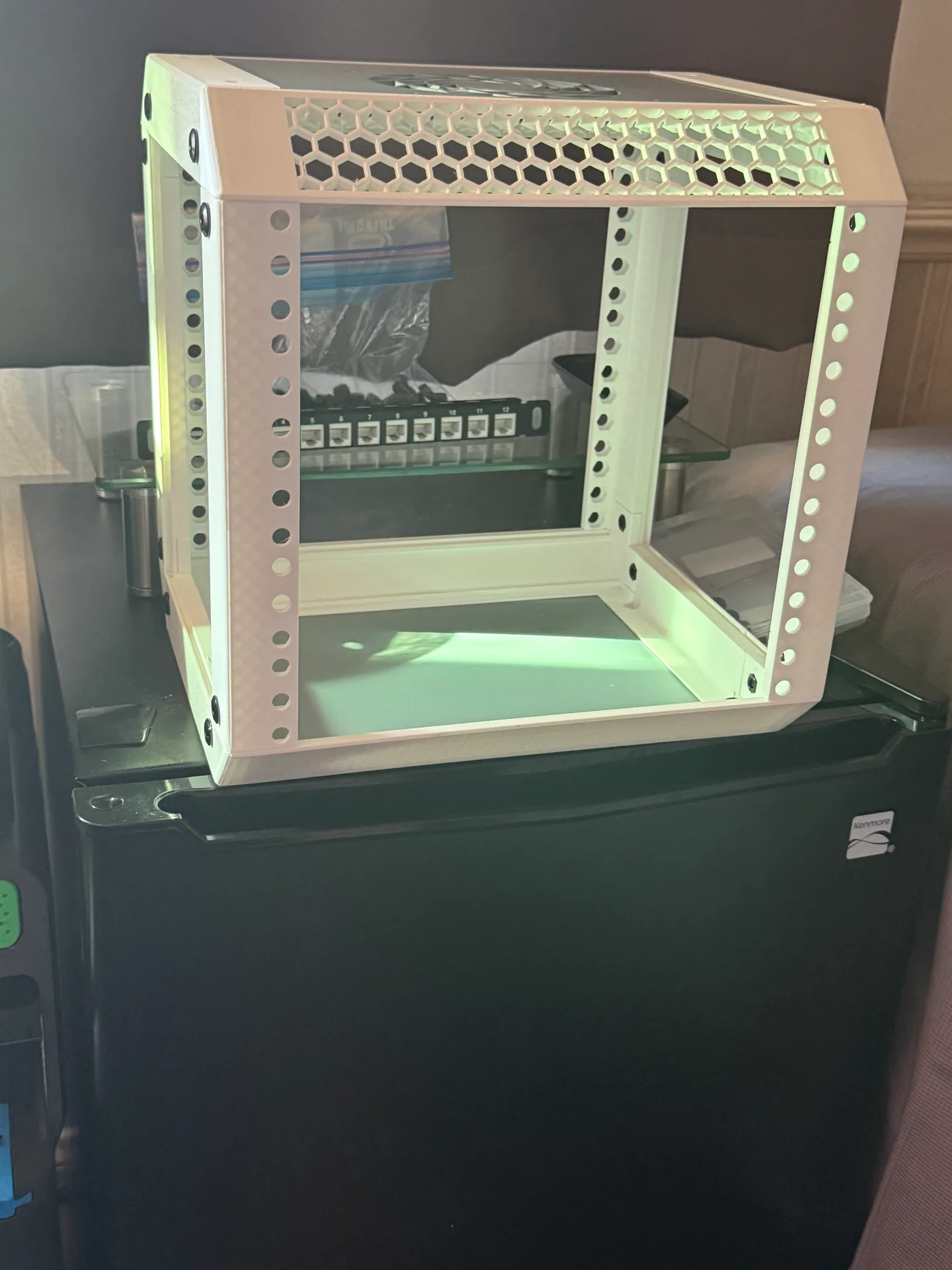
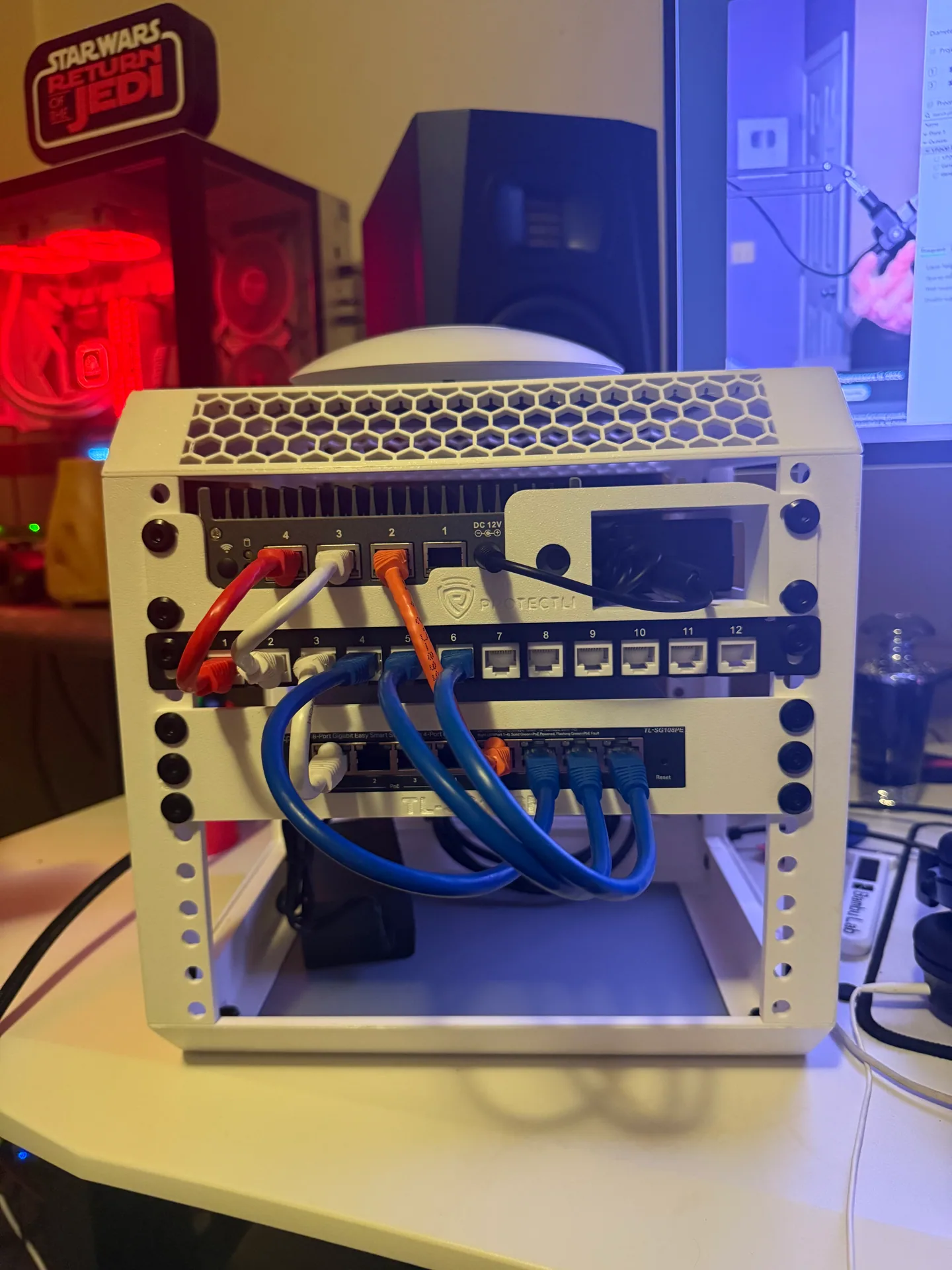
I 3D printed the frame and built up the hardware in stages, starting with the Protectli router, switch and patch panel.
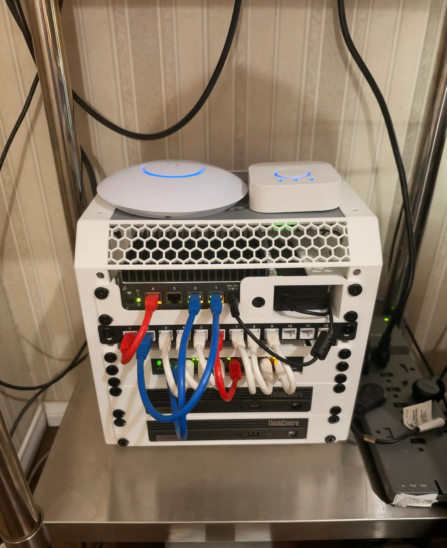
The expanded setup now includes two mini PCs that I plan to add to my cluster.
 View photo
The frame assembled before the network hardware went in.
 View photo
The Protectli router, switch and patch panel fitted and connected.
View photo
The fuller setup, including two mini PCs planned for my cluster.